
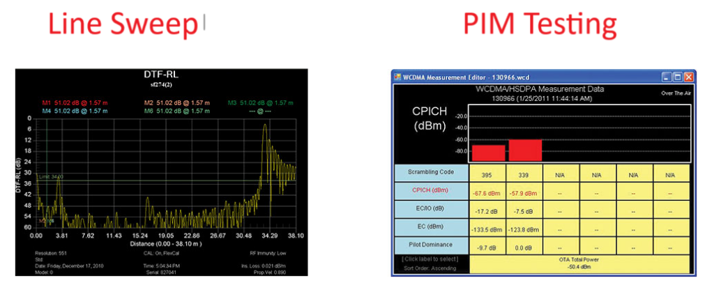
Line sweep basics
Cellular system performance starts with correct line sweep measurements. This acceptance test is usually broken down into two basic tests: Return loss and insertion loss. Both are very frequency dependant and can vary greatly within a specified band.
Return loss measures the power transfer efficiency of the antenna system. It is essential that minimal power is reflected back towards the transmitter. Any reflected power can distort the transmitted signal and when powerful enough, cause damage to the transmitter. A return loss figure of 20 dB indicates that 1% of the transmitted signal is being reflected back to the transmitter and 99% is reaching the antenna, this is generally considered good performance. A return loss of 10 dB indicates that 10% of the signal is being reflected and should be considered poor. If the return loss measured 0dB, 100% of the power would be reflected, this would likely be an open or short circuit. Every connection erodes the possible return loss and thus minimal connections are recommended. Return loss can be masked by high insertion loss and this is why DTF plots are sometimes requested.
Insertion loss measures the amount of signal loss through a coaxial system. Ideally the insertion loss will be very low. Again, every connection adds to the system loss. If a cable has 3 dB of insertion loss, 50% of the power is being lost within the cable system. This effectively turns a 16 watt transmitter into an 8 watt transmitter. High loss affects the site’s ability to not only get signals out to the subscribers, but heavily affect the handsets ability to transmit back to the BTS receivers. Both problems can seem very slight but do drastically affect the subscribers’ user experience in reduced coverage area and short handset battery life.
Cell site insertion loss is commonly measured with a short circuit attached to the top end of the cable and site master measuring return loss at the bottom end. The signal will travel up the cable. When it reaches the short circuit 100% will reflect back down to the instrument. In this test scenario, the signal experiences the cable loss twice (up and down) so the final figure should be divided by 2. A measurement of 3dB will equate to an insertion loss of 1.5dB. As requirements vary greatly between operators, specific operator test procedures must be used in all cases to ensure compliance of test results.
While system designers take this information into account when designing the site specifications, it is important to be aware of the effects that insertion loss and cable return loss can have on the overall system return loss. A very good system return loss can mask possible component / antenna problems and therefore may not be a good thing; it could easily be due to a cable that exhibits high insertion loss and a faulty antenna. As a result, a smaller than expected signal level would reach the antenna and a large percentage would be reflected, only to be dissipated within the high loss cable. This results in a transmitted signal level much lower than expected and the coverage area would be restricted greatly. Comprehensive testing is required.
PIM test characteristics
PIM testing is a measure of linearity within a cellular transmission system. It is a very comprehensive test of mechanical integrity. Two high power test signals are injected into the antenna line. If any corroded, dirty or mechanically compromised connections or components exist, the two test signals will mix and produce intermodulation. When performing PIM tests, the test system usually monitors the 3rd order product as it is the strongest of all intermodulation orders. By minimizing the 3rd order products, all other intermodulation is also minimized. Some site configurations cannot generate PIM, particularly if only one Transmitter is used. There is still a compelling argument to perform PIM testing on these smaller sites to ensure that further expansion will yield excellent performance, as the RF plumbing will be in great operating condition and suitable for multi carrier operation. A methodical approach must be followed when PIM testing as continual breaking of connections will cause premature failure, particularly when testing antennas and TTLNA’s.
Sites that have multiple transmitters will show performance degradation from internally generated PIM when poor connections exist. This may become apparent with Rx noise imbalance alarms and dropped calls/early handoff. The BTS supervisory system should inform the operator of these conditions. In cases like these, repairing the connections/antennas/linearity problems with a PIM tester is the only real solution. Unfortunately, a large percentage of old sites fall into this category.
The difference between Line Sweeping and PIM testing
Line Sweep testing and PIM are very different tests. Both are very important and accurate measures of a cell site’s ability to provide service and perform optimally. Line sweeping measures the signal losses and reflections of the transmission system. PIM testing is a measure of construction quality and poor quality will result in self-interference.
PIM testing performance measurements are not relevant unless accompanied by comprehensive line sweep tests. It is important to recognize that PIM test measurements performed on a transmission system that has poor microwave performance are irrelevant indicators of the performance of the transmission system. Unfortunately, lack of understanding of the way these tests relate to performance has not only resulted in compromised test data, it also causes the need to re-test the systems repeatedly. In turn, connections and components are becoming increasingly overworked and greatly contributes to line sweep and PIM problems.
PIM requires both low system loss and good return loss (VSWR) to perform to an acceptable standard. If PIM testing is performed prior to line sweep testing the operator may not be aware of the impedance characteristics of the transmission line. High insertion loss attenuates the PIM test signals preventing the high power characteristics from reaching the very components which require this stringent testing. Poor Return loss reflects a percentage of the PIM test signals back into the test set causing some signal cancellation that can report a false positive.
It is becoming increasingly common to take advantage of poor line sweep performance to pass a PIM test.
By performing the line sweep test prior to PIM testing, the operator can be confident the insertion loss and return loss data at acceptable levels. This data in turn ensures that the PIM test signals actually reach the components at the highest possible signal level, offering the most accurate indicator of true PIM performance. By constructing a system using modern low PIM practices, the need to break the transmission system back open will be minimized. If the lines are disassembled again to repair or clean a connector, the line sweep data will need to be repeated.